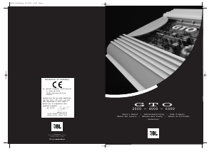
Thank you for purchasing
a JBL GTO amplifier. In
order that we may better
serve you should you
require warranty servi-
ce on your new ampli-
fier, please retain your
original purchase receipt
and return the enclosed
warranty
registration card.
Important: Installation of
automotive ste-
reo
components can require
extensive experience in
performing a variety of
mechanical and electrical
procedures. Although
these instructions
explain, in a general
sense, how to install GTO
amplifiers, they may not
show the exact installa-
tion methods for your
particular vehicle. If you
feel you lack the tools or
necessary
experience, ask
your
authorized JBL car-audio
dealer about professional
installation options.
Installation Warnings
and Tips
• Always wear pro-
tective eyewear when
using tools.
• Turn off all audio
systems and other elec-
trical devices before
you start.
• Disconnect the
negative (-) lead from
your vehicle’s
battery.
• Check clearances
on both sides of a plan -
ned mounting surface
before drilling any
holes or installing any
screws. Remember that
the screws can extend
behind the surface.
• At the installation
sites,
locate and make a note of
all fuel lines, hydraulic
brake lines, vacuum
lines and
electrical wiring. Use
extreme caution when
cutting or drilling in
and around these areas.
• Before drilling or
cutting holes, use a uti -
lity knife to remove
unwanted fabric or
vinyl to keep material
from snagging in a drill
bit.
• When routing
cables, keep input-
signal cables away from
power cables and spea-
ker wires.
• When making
connections, ensure that
they are secure and
properly insulated.
• If the amplifier’s
fuse must be replaced,
use only the same type
and rating as that of the
original. Do not substi-
tute another kind.
Warning: Playing loud
music in an automobile
can permanently damage
your hearing as well as
hinder your ability to
hear traffic. W e recom-
mend listening at low
levels while in your car.
JBL accepts no liability
for hearing loss, bodily
injury or property
damage resulting from
use or misuse of this
Wiring the Input-Signal Connections
Connect a pair of signal cables with RCA-type ends
between the connectors on the amplifier and the RCA-
type signal connectors on the source unit. If your
radio has only speaker-level outputs, you must pur-
chase a speaker-level-to-line-level adapter,
commonly sold as an accessory.
System Setup and Adjustement
Refer to figures 1-3 for location of adjustement
switches and controls.
Electronic Crossover
The electronic crossover can be selected as a 12dB/oct
high-pass filter (HPF), 12dB/oct low-pass filter
(LPF) or it can be defeated (OFF). The crossover fre-
quency can be set at any
frequency between 30Hz and 320Hz.
Input Sensitivity
initially, turn the input-sensitivity LEVEL control to
its maximum (counterclockwise) position. Turn on
the source unit and
increase the volume control until it is approximately
three-
quarters of maximum-output level. Slowly increase
the input LEVEL control (clockwise) while listening
to the quality of the reproduced sound. When you hear
distortion on the music peaks, turn the LEVEL control
back slightly. This is the maximum undistorted output
level of your system. Turning the LEVEL control up
farther WILL N OT INCREASE THE OUTPUT POWER OF
YOUR AMP! It will only decrease the amount of volu-
me control rotation before the amp is at full output
power. It will also increase the amount of extraneous
noise in your system.
Choosing a Location and Mounting the Amplifier
Amplifiers need air to stay cool. Suitable locations are
under seats (provided the amplifier doesn’t interfere
with the
seat-adjustement mechanism), in the trunk or in any
location that provides enough air for the amp to cool
itself. Do not mount the amplifier with the heat-sink
fins facing downward; this makes convection cooling of
the amplifier impossible.
Mount the amplifier so that it is not damaged by the
feet of back-seat passengers or shifting cargo in the
trunk. Mount the amplifier so that it remains dry -
never mount an amplifier
outside the car or in the engine compartment.
Using the amplifier as a template, mark the location of
the mounting holes on the mounting surface, drill
pilot holes and attach the amplifier to the mounting
surface with screws. Make sure the amplifier is
mounted securely.
Wiring the Power Connections
Refer to Figures 1-3 for connector locations. Use at
least 6 mm
2
wire for power and ground connections.
For power, remote and ground connections strip off
one end of each jacket to reveal bare wire for inser-
tion into the
barrier-strip connectors. Connect a wire from the
GND
connector on the amplifier to the nearest bare-metal
chassis component; scrape away the paint to ensure
good
conductivity. Next, connect a wire between the BATT
terminal on the amplifier and the POS (+) terminal of
the vehicle’s
battery. Pass the wire through a factory-installed
grommet in the firewall, or install a grommet if a
factory grommet is not
available. You must install, within 45 cm of the bat-
tery
connection, a fuse holder and fuse with the same rating
as the fuse in the amplifier’s chassis. This will pre -
vent a short circuit from causing damage to the
amplifier or the car. Connect a wire
between the REM terminal of the
amplifier and the
“remote out” or power-antenna lead
on the vehicle’s radio.
Wiring the Speaker-Output Connections
Connect the speakers, observing proper polarity, to
the speaker-output barrier
strip. The total impedance
of the speaker system
connected to the amplifier
when the amplifier is
driven in stereo must be at
least two ohms.
If you are bridging the
amplifier, connect the speaker
wires to the terminals marked
“bridged”, observing proper polarity. The total
impedance of the speaker system connected to the
amplifier must be at least four ohms in bridged mode.
If you are running the amp in Tri-Mode (stereo and
mono simultaneously), connect the satellite speakers
to the
speaker connector as you would a pair of stereo spea-
kers. Connect the subwoofer to the terminals marked
FREQUENCY INDUCTOR CAPACITOR
Crossover 6dB/oct. LP (4 ohm) 6dB/oct. HP (4
ohm)
75Hz 8.0mH 530µF
100Hz 6.4mH 400µF
125Hz 5.0mH 318µF
150Hz 4.2mH 265µF
175Hz 3.6mH 227µF
Troubleshooting
Symptom Likely Cause Solution
No audio (power indicator is on) Speakers or input-signal cables dis-
connected; Check connections, source, speakers.
defective speaker or source unit
No audio (power indicator is off) No voltage at BATT or REM terminals;
Check voltage at amplifier terminals with VOM.
bad ground connection. Repair faulty connection.
No audio (power indicator is off) Amplifier protection is engaged due to
Disconnect speaker leads one at a time to
overheating; shorted or defective speaker determine which speaker or wire is
shorted or
or speaker cable. defective.
Repair the short circuit or replace bad
Specifications GTO 2000 GTO 4000 GTO 6000
Power Output max.: 400 watts 600 watts 1100 watts
RMSBridged Power Output, 4 Ohm:
220 watts 300 watts 550 watts
RMSPower Output, 2 Ohm: 2 x 110 watts 4 x 75 watts 4 x 75/2 x 125 watts
RMSPower Output, 4 Ohm: 2 x 75 watts 4 x 50 watts 4 x 50/2 x 75 watts
THD@Rated Output: 0.10% 0.10% 0.10%
SNR (A-weighted): >92dB >92dB >92dB
Frequency response: 1 0 H z - 4 0k H z 1 0 H z - 40kHz 10Hz-40kHz
Active crossover (cont. var.): 30-320Hz 30-320Hz 30-320Hz
Crossover settings: LP/HP/off LP/HP/off HP/off + LP/off
Crossover slope: 12dB 12dB 12dB
Input sensitivity: 100mV-4V 100mV-4V 100mV-4V
Bass boost: +6db@45Hz +6db@45Hz +6db@45Hz
Dimensions (L x W x H): 358 x 294 x 55 mm 358 x 294 x 55 mm 568 x 294 x 55 mm
Weight: 4 kg 4 kg 6 kg
Note: Bridging of GTO 6000
+-
Front R + L-
Rear R + L-
Sub R+ L-
Fig.1 GTO 2000
Fig.2 GTO 4000
Fig.3 GTO 6000


Partecipa alla conversazione su questo prodotto
Qui puoi condividere cosa pensi di JBL GTO4000 Amplificatore auto. Se hai una domanda, leggi prima attentamente il manuale. La richiesta di un manuale può essere effettuata utilizzando il nostro modulo di contatto.