
This product is designed according to EN 60730-2-9 and EN60730-2-7 standards, in compliance with
the applicable EC directives, and made in Italy.
Power supply: Alkaline Batteries 2x1,5V LR6 (Type AA)
Battery life >1year
Maximum contact rating: 5A(1A) 250VAC
Action type: 1B
ErP class I (+1%) - 811/2013 (ON/OFF regulation)
ErP class IV (+2%) - 811/2013 (TPI regulation)
Operating Temperature: 0°C ÷ 50°C
Display temperature range: 0°C÷39°C
Regulation temperature range: 5°C ÷ 30°C
Temperature resolution: 0,1°C
Temperature differential (ON/OFF regulation): from 0,1°C to 2,0°C (std. 0,2°C)
Temperature sensor: NTC 100KΩ@25°C
Protection degree: IP20
Insulation class: Type II (double insulation)
Pollution degree: 2
Software: class A
Heat and fire resistance: Category D
Storage temperature: -25÷60°C
Rated impulse withstand voltage 2,5kV
Installation: on wall
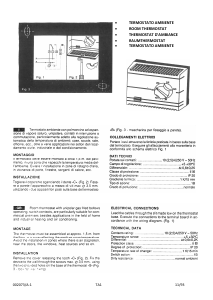
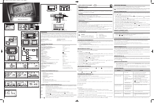
Place this device far from any heat source or air flow, at about a 1,5mt height from the floor. Open the
device pushing the clip on the base right side (Fig.1-1) then rotate the front cover leftward (Fig.1-2)
and lift slightly to unfasten it (Fig.1-3).
Remove the two screws (Fig.2-D) fixing the inner protection cover for the electrical connections.
Rotate leftward and release it. Fix the base on to the wall, using the horizontal (Fig.2,A-A or A-B) or
the vertical (Fig.2, C-C) holes. Take care to dispose the cables in a proper manner through the window
on the bottom of the base. Connect the wires to the terminal block according to the schematics (Fig.3)
and place the protective inner cover again over the electric parts. Fix the screws (Fig.2-D). Dispose
the optional external probe cable separately from the relay thermostat connection wires. Insert the
batteries in their compartment on the display board as described (Fig.4). To close the device proceed as
in the (Fig.1), reversing the sequence of operations: pairing the two left parts (Fig.1-3) then turn the
front to the right side (Fig.1-2) until the hook (Fig.1-1) clicks on the base.
When the symbol
(batteries discharged) flashes on the display, the batteries must be replaced as
soon as possible.
In this situation, the clock thermostat will keep on working properly for a short period of time, after
which the system will be turned off permanently using the energy left over in the batteries. From this
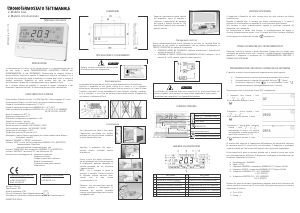
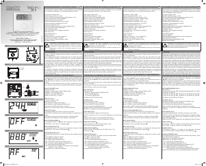
4-digit multifunction indicator for temperature display,
reduced set point, clock and user / installer settings.
Set display backlit brightness.
View or set the clock
Summer mode (conditioning)
Winter mode (heating)
System ON (conditioning)
System ON (heating)
View or set reduced T2 Set Point
Batteries discharged
FIRST START
Setting the clock
• Set the hours by + and - then OK.
• Set the minutes by + and - then OK.
The device switches to OFF mode.
OFF MODE
The display shows OFF and the anti-frost function is active..
Press Mode to browse active modes (Manual mode, Automatic mode, OFF mode).
AUTOMATIC MODE
In AUTOMATIC mode the thermostat sets the ambient temperature at the Comfort or Reduced T2 values,
according to the programming of the micro switches.
The display show AUTO to identify this modality.
SETTING THE TIME PROGRAMME
The device is equipped with a row of micro switches with 24 levers that correspond to the time slots
in a day. The time programme is easy to set; simply push the levers upward (position T1) for the hours
in which you want to have a COMFORT temperature, and push them downward for the hours in which
you want a REDUCED T2 temperature.
SETTING THE COMFORT TEMPERATURE
You can always set COMFORT temperature by turning the central knob to the value required.
You can change the temperature between 5°C and 30°C in both winter and summer operation.
SETTING THE REDUCED T2 TEMPERATURE
The REDUCED T2 temperature is set by pressing button + and -
You can change the temperature between 5°C and 30°C in 0.1°C increments in both winter and summer
operation. During the setting, the icon
flashes until the new value is stored.
MANUAL MODE
In MANUAL mode the thermostat sets the ambient temperature at the COMFORT temperature, regardless
of how the micro switches are programmed.
SETTINGS MENU
In OFF mode, press the SET key to enter in the settings menu. The SET icon will be displayed to confirm
the operation. Press again SET to browse the available options.
1. Set Winter/Summer mode. Icon or flashing.
Press + or - to set Summer mode ( ) or Winter mode ( ).
2. Set clock. Icon flashing.
Press + or - to set the clock.
3. Set backlit brightness. Icon flashing.
Press + or - to set the brightness.
INSTALLER MENU
In OFF mode, press and hold + and - simultaneously for 10 seconds to enter in the menu. The SET
and MAN icons will be displayed confirming the operation. Press again SET to browse the available
parameters.
1. Parameter P01 -> Set antifrost threshold (standard 6.0°C)
Press + or - to modify the value. Press SET to confirm.
2. Parameter P02 -> Switching differential in ON/OFF regulation (standard 0.2°C)
Press + or - to modify the value. Press SET to confirm.
3. Parameter P03 -> Temperature calibration (standard 0.0°C)
Press + or - to modify the value. Press SET to confirm.
4. Parameter P04 -> Set regulation mode
Press + or - to modify the value :
0) Regulation mode ON/OFF
1) Regulation mode TPI for radiator systems
2) Regulation mode TPI for floorsystems
Press SET to confirm. At the end of the settings, press MODE to return to the OFF state.
PRODUCT DESCRIPTION AND TECHNICAL SPECIFICATIONS
INSTALLATION
REPLACING THE BATTERIES
DISPLAYED SYMBOLS LEGEND
DESCRIPTION OF COMMANDS AND OPERATIONS (FIG.5)
EN
Fig. 1
Fig. 2
Fig. 3
Fig. 4
Fig. 5
6 /
Mode
Set /
5
15
10
20
25
30
10
0
5 7
9
6 8 11
14
18 22
16 20
13 17 21
15 19 23
12
5 /
1
2
1
2
8 /
1
2
7 /
1
2
1
D
A
A
A-A=83.5 mm
A-B=60 mm
C-C=60 mm
B
C
C
D
NC
NO
C
C
NC
NO
NC
NO
C
- +
+ -
6 /
Mode
Set /
5
15
10
20
25
30
10
0
5 7
9
6 8 11
14
18 22
16 20
13 17 21
15 19 23
12
5 /
1
2
1
2
8 /
1
2
7 /
1
2
6 /
Mode
Set /
5
15
10
20
25
30
10
0
5 7
9
6 8 11
14
18 22
16 20
13 17 21
15 19 23
12
5 /
1
2
1
2
8 /
1
2
7 /
1
2
2
3
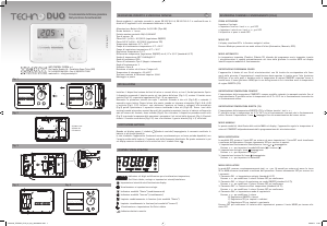
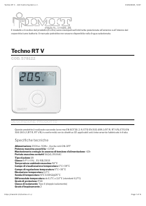
DUO
Cronotermostato elettronico giornaliero
Daily electronic chronothermostat
07B106 Rev0617
IMIT CONTROL SYSTEM s.r.l.
Via Varallo Pombia,19 - Castelletto Sopra Ticino (NO)
Tel (+39)0331941600 - Fax (+39)0331973100
Manuale_TECHNO_DUO_ita_eng_420x285mm.indd 2 06/06/17 17:09


Partecipa alla conversazione su questo prodotto
Qui puoi condividere cosa pensi di IMIT 578160 Techno Duo Termostato. Se hai una domanda, leggi prima attentamente il manuale. La richiesta di un manuale può essere effettuata utilizzando il nostro modulo di contatto.
rispondi | È stato utile (2)
rispondi | È stato utile (0)